PhantomPi: A Covert Red Team Implant (Part 1)

In black-box red team operations, physical access can be a legitimate option for initial compromise. During one of these engagements, the plan was simple in concept: clone an employee badge, bypass access control, and leave behind a device that would act as a stealthy, persistent pivot into the internal network. The biggest challenge, though, arose when we discussed which device could truly meet those requirements: execution required more than a stock travel router or any off-the-shelf box left behind a desk. The implant had to blend in, bridge transparently, maintain a cellular (4G/LTE) control channel, survive for months, and provide operators with a reliable path even if the corporate LAN lacked internet egress. This article revisits the thought process, choices, and technical decisions made during the implant’s design and implementation.
This article covers the first part of the implant’s technical overview. Part 2 will cover the bridge implementation, NAC bypass, device spoofing, and the design of the 3D-printed case used to hide components and camouflage the implant.
This project was developed during my work at InTheCyber Group. Visit the InTheCyber Blog for more posts.
1. Introduction: Why Build a Red Team Implant?
1.1 The operation context
Assume a black-box red-team engagement in which physical entry is the primary option for initial access. The objective is to obtain quiet entry (through badge cloning, social engineering, or other means) and deploy an implant that provides a remote, persistent pivot inside the network, controllable, inconspicuous, and engineered for long-term resilience.
1.2 Implant concept, purpose, and field constraints
The implant is a compact, purpose-built system intended to stay effective under unknown on-site conditions. It should blend into typical network environments, avoid unnecessary attention, and keep operators connected even when the LAN has no Internet egress. Below are the primary characteristics and features the implant needs to satisfy.
Operating modes. The preferred mode is inline bridging between a legitimate asset and the corporate switch, so the environment continues to “see” the original device while a pivot is gained. In bridge mode, the implant adopts or imitates the inline asset’s identity (hostname, IP, MAC) to avoid creating suspicious fingerprints. When inline placement is not possible, the implant can attach as a standalone node on the internal network, which is functional but less stealthy.
NAC awareness. In bridge mode, EAPOL and related exchanges have to be passed transparently so the network continues to authenticate the legitimate asset, while the implant maintains connectivity on the same link, effectively bypassing these controls.
Reachability. Assume the internal LAN cannot reach the Internet. Out-of-band access have to be provided over 4G/LTE, with a hardened VPN so operators can connect even without LAN egress.
Emergency local access. If the cellular path fails while nearby, we must have fallback options such as a hidden Wi-Fi access point or a small status display and button to enable last-mile troubleshooting.
Power and installation. Mains power or PoE are preferred, but if neither is present, a battery or power-bank mode should be available, with remote on/off control to conserve power when inactive. In addition, form factor and enclosure matter, so we want to avoid exposed PCBs, keep cabling tidy, and use neutral finishes that blend with network gear.
Resilience. The system must tolerate reboots, power glitches, and long unattended periods, with reliable recovery paths suited for engagements lasting weeks or months. Resilience should be treated as a first-class feature by using hardware watchdogs, robust boot flows, and safe recovery procedures to ensure the device remains reachable.
1.3 Key design requirements
In summary, these are the core requirements:
- Covert form factor & camouflage (no exposed PCB, subdued indicators, tidy wiring).
- MITM bridge first, with identity mimicry to avoid introducing new assets on the LAN.
- Independent reachability via LTE + always-on VPN, assuming no LAN egress.
- Power flexibility: mains power or PoE when possible, battery with remote power control as contingency.
- Operational resilience: watchdogs, safe boots, auto-heal on crashes, persistent logs.
- NAC-aware behavior: transparent 802.1X pass-through so the network continues to authenticate the inline asset while the implant stays connected on the same link.
- Field-friendly ops: emergency local access (hidden AP/screen+button)
2. Hardware Components
The focus first is on the hardware, breaking the implant down and rebuilding it component by component.
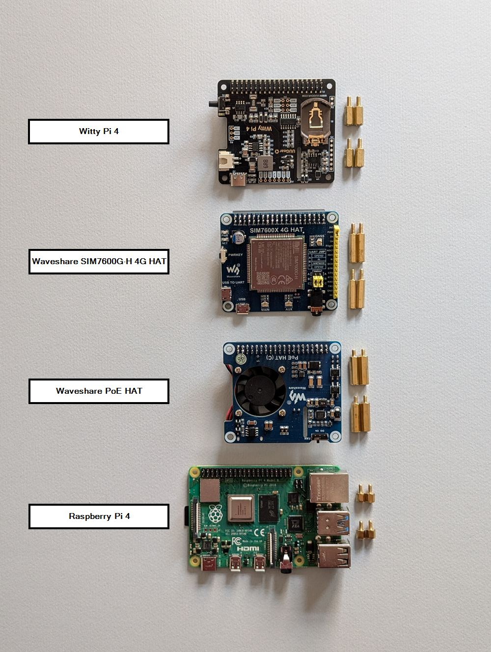 Hardware components overview
2.1 Core compute: a Raspberry Pi 4
Let’s start with the main board: the Raspberry Pi 4. It is powerful enough to favor performance and operator comfort, yet still small. It has a rich HAT ecosystem and the necessary hardware characteristics to run a bridge cleanly, pivot traffic, and even run tools locally when needed. There are smaller or lower-power options, and future iterations could swap the board, but for this kind of engagement the Pi 4 hit the balance needed.
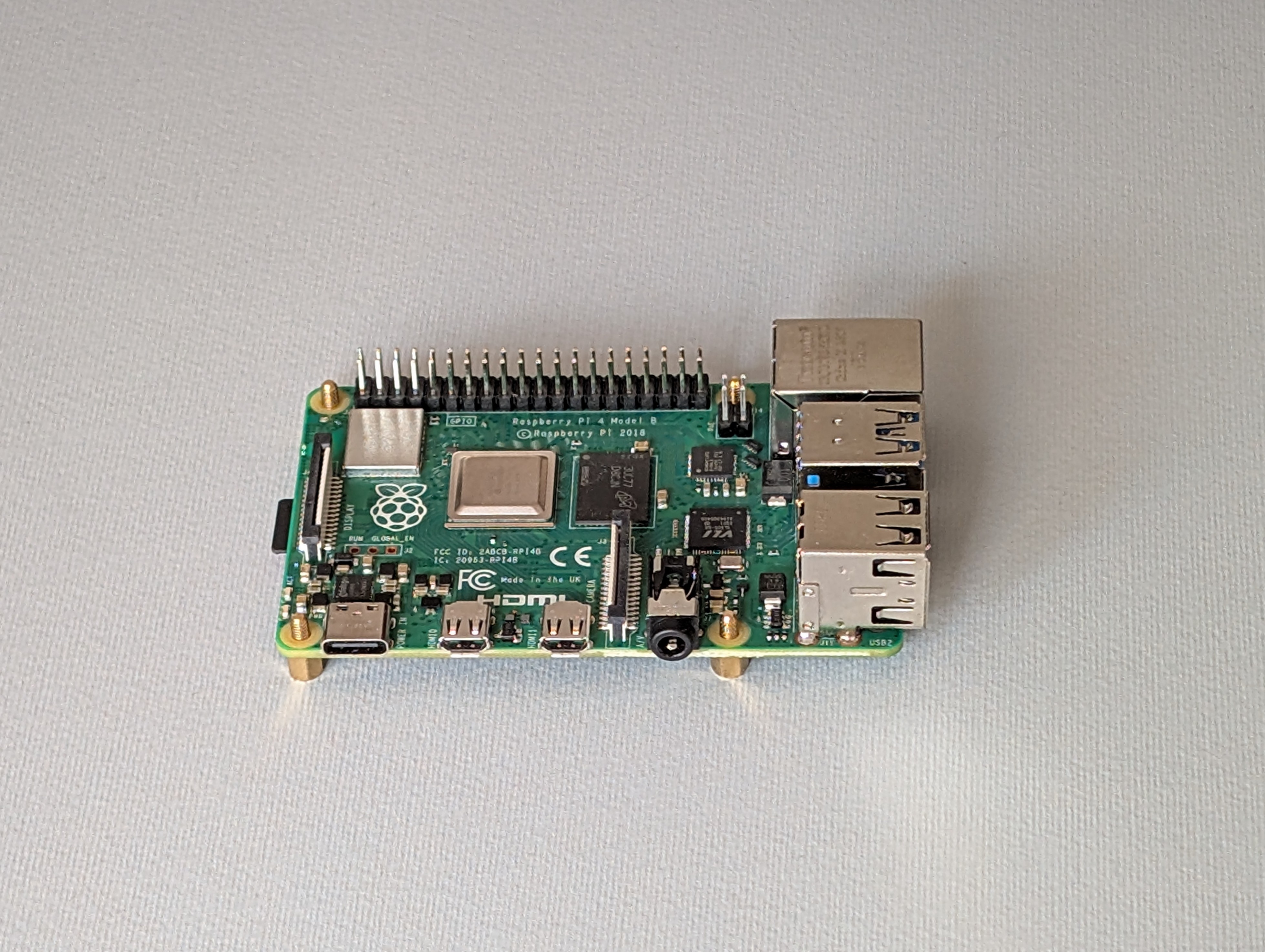 Raspberry Pi 4
2.2 Power via Ethernet: PoE HAT
PoE support is essential in the field. The Waveshare PoE HAT lets the Pi draw power from the Ethernet link when the switch or injector provides it, which extends the implant’s flexibility during installation. It reduces extra cabling when mains outlets are not available or easily accessible, which is valuable when working quickly in a red team scenario.
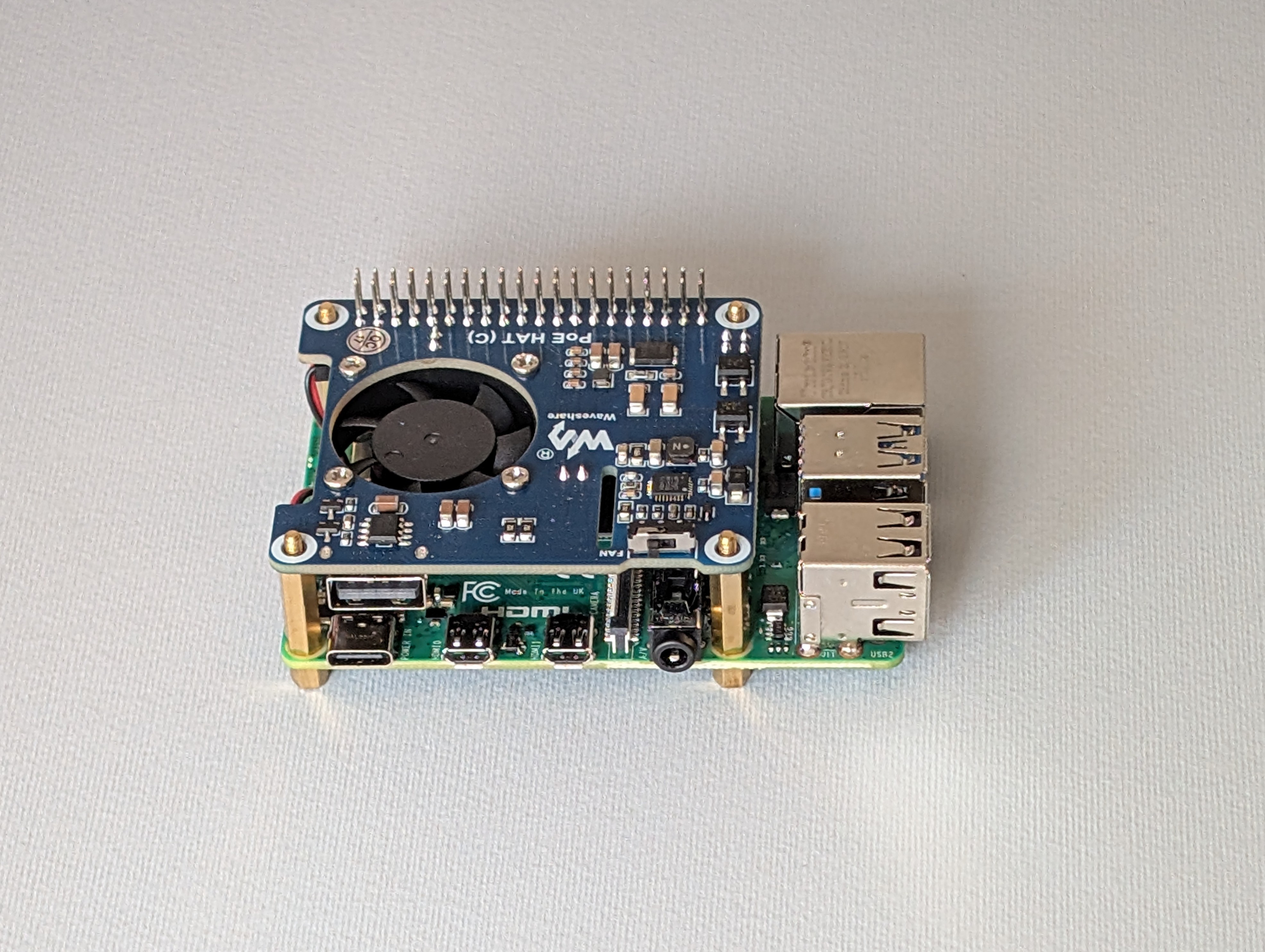 PoE HAT mounted on Raspberry Pi
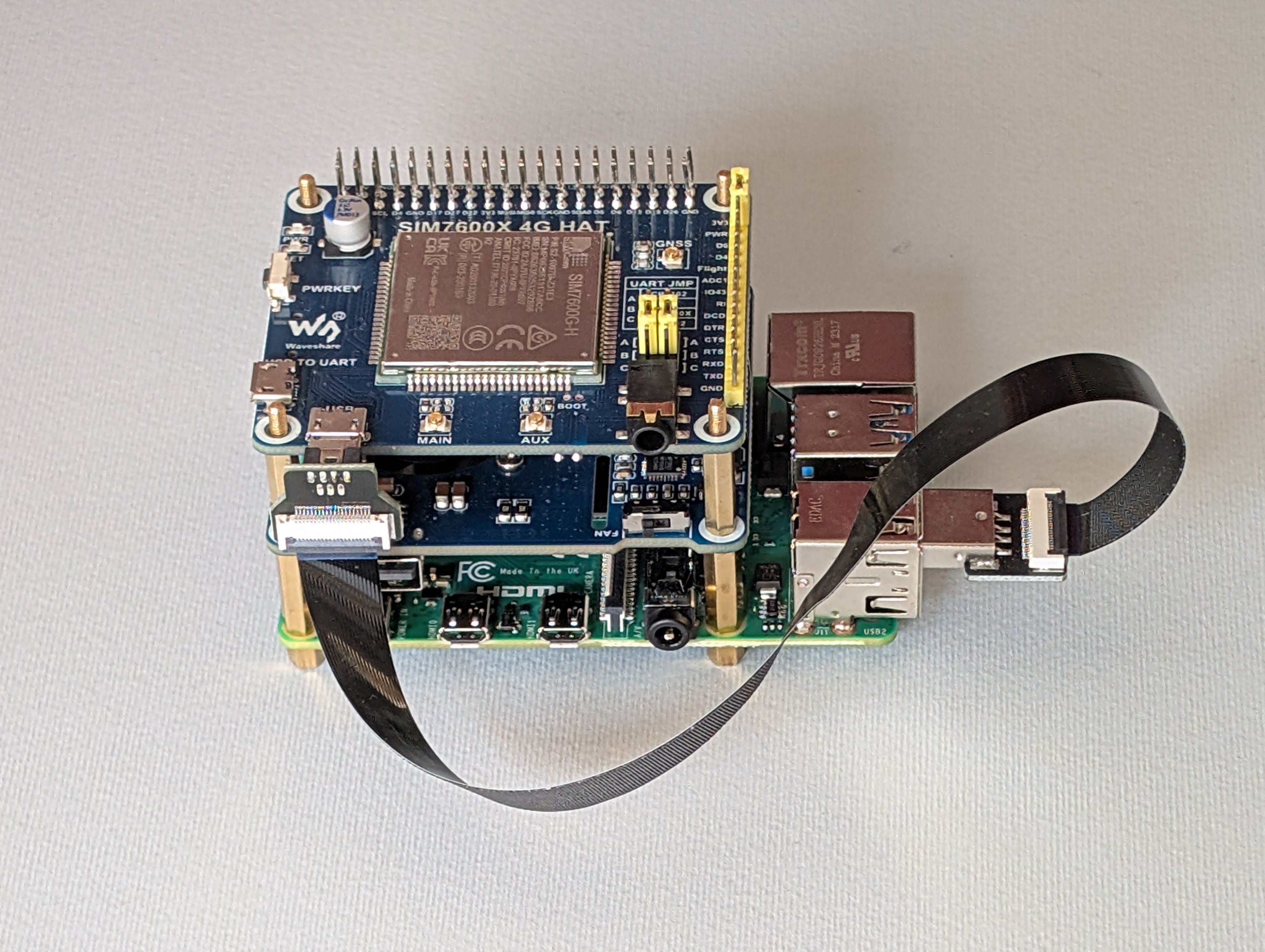
2.3 Out-of-band path: LTE modem (SIM7600G-H)
To provide Internet access over the cellular network, a Waveshare SIM7600G-H HAT have been used with an IoT data SIM. Two external antennas are attached via RP-SMA leads to further improve signal. The modem connects to the Pi with a micro-USB to USB-A cable. The modem is configured in RNDIS mode, which presents it as a USB network interface on the Pi. This gives the implant a self-contained Internet uplink and allows the box to auto-join a WireGuard VPN for operator access.
 SIM7600G-H 4G HAT
Modem configuration is possible by connecting to the serial device under /dev/ (sudo minicom -D /dev/ttyUSB2) and sending AT commands. The main configurations needed are the command to set RNDIS mode (AT+CUSBPIDSWITCH=9011,1,1), the commands to get or set the APN depending on the SIM used (respectively AT+CGDCONT? and AT+CGDCONT=1,"IP","<apn-name>"), and the reboot command, which can be useful as a quick remediation in case of issues (AT+CFUN=1,1).
These main operations are wrapped in a single Bash script at /opt/implant/scripts/modem-config.sh, available system-wide to make configuration straightforward and more user-friendly, even without knowing every AT command.
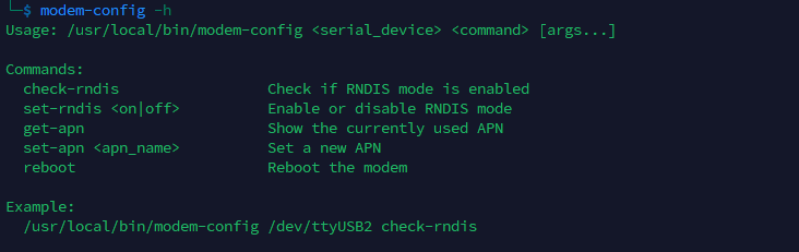 modem-config helper script
2.4 Power management: Witty Pi 4
The Witty Pi 4 (UUGear) manages power for the whole stack when PoE is not the power source. The USB-C power input is routed into Witty Pi, which then powers the Pi and the attached modules. Scheduling power on or off is handled by Witty Pi software and its onboard sensors.
 Witty Pi 4 mounted
As shown in the diagram below from the Witty Pi User Manual, a dedicated control line handles power switching, and an I²C interface is used for tasks like reading onboard temperature sensor data and accessing the RTC (Real-Time Clock), which stays in sync with the Raspberry Pi’s clock so it knows exactly when to power the system back on according to the defined schedule.
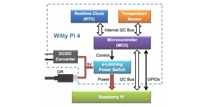 Witty Pi 4 architecture diagram
Configuration is straightforward and can be done using the provided bash script or the web GUI.
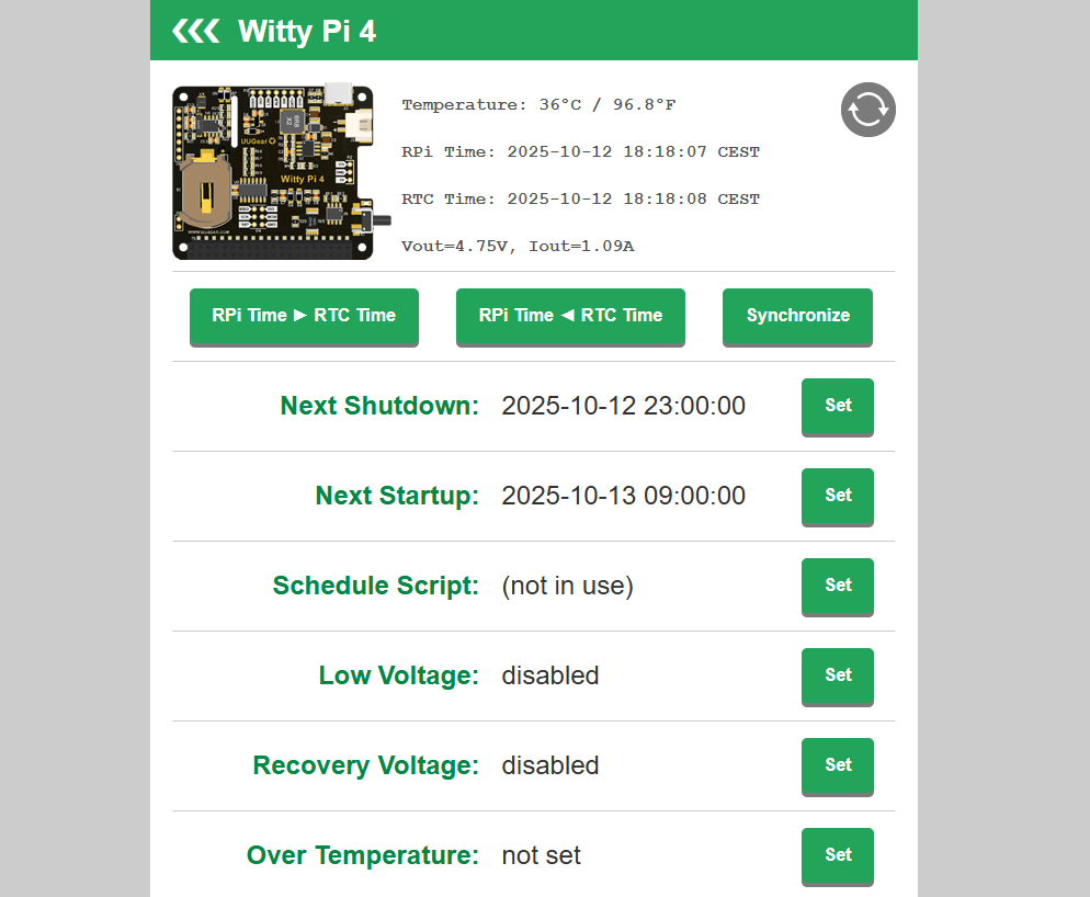 Witty Pi 4 web GUI
In edge cases where a battery is the only option, remote on/off scheduling helps stretch limited power and keep the implant usable as long as possible, while optimizing energy consumption. It also allows the device to be turned on or off automatically based on configured temperature thresholds to protect the hardware.
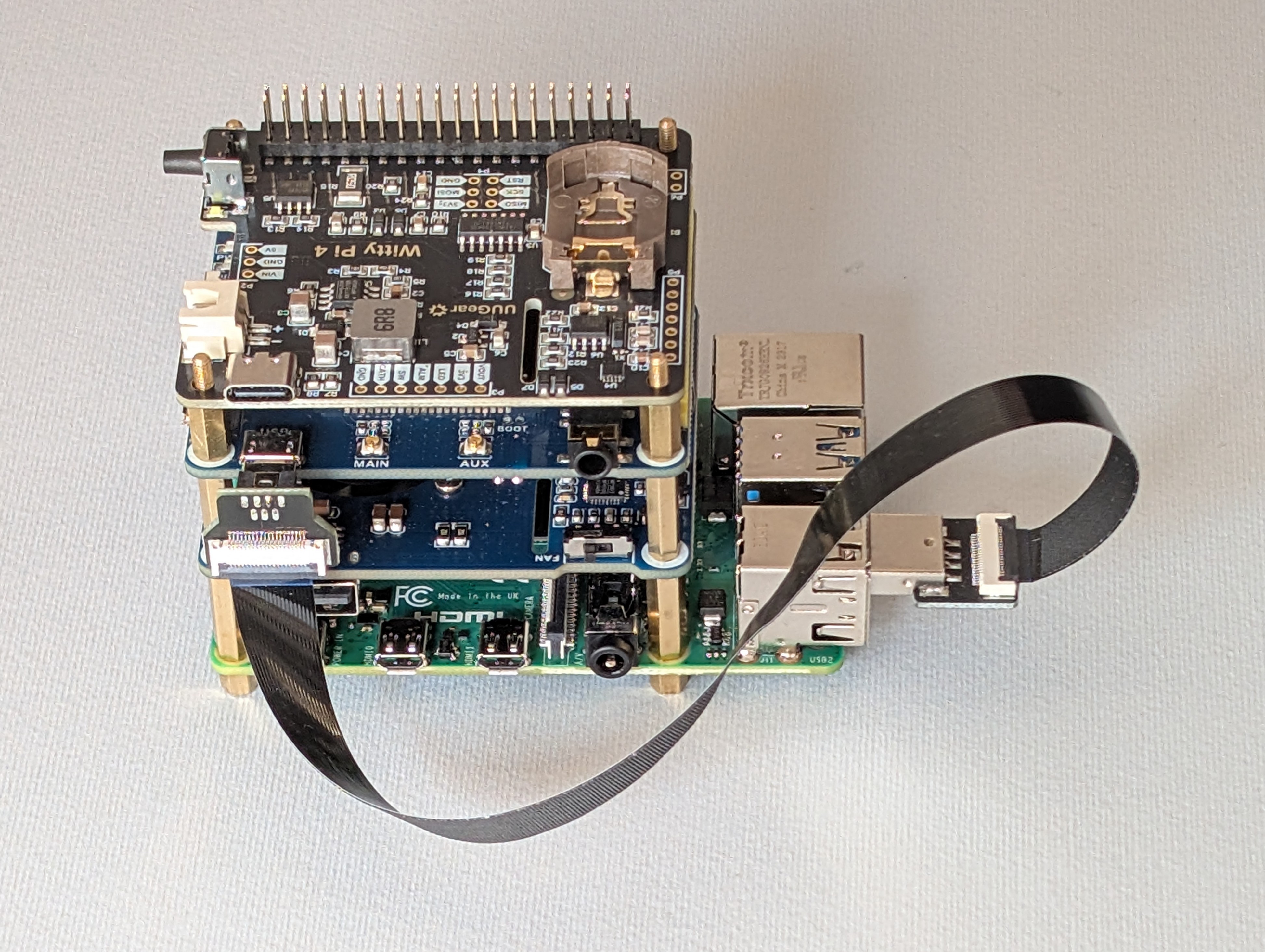
2.5 Second Ethernet: USB-to-Ethernet adapter
Bridging requires two physical Ethernet ports: one facing the corporate switch (internal network) and one facing the inline device. This allows the implant to forward frames transparently. Since the Pi 4 has only one onboard port, a USB-to-Ethernet adapter was added to provide the second side of the bridge.
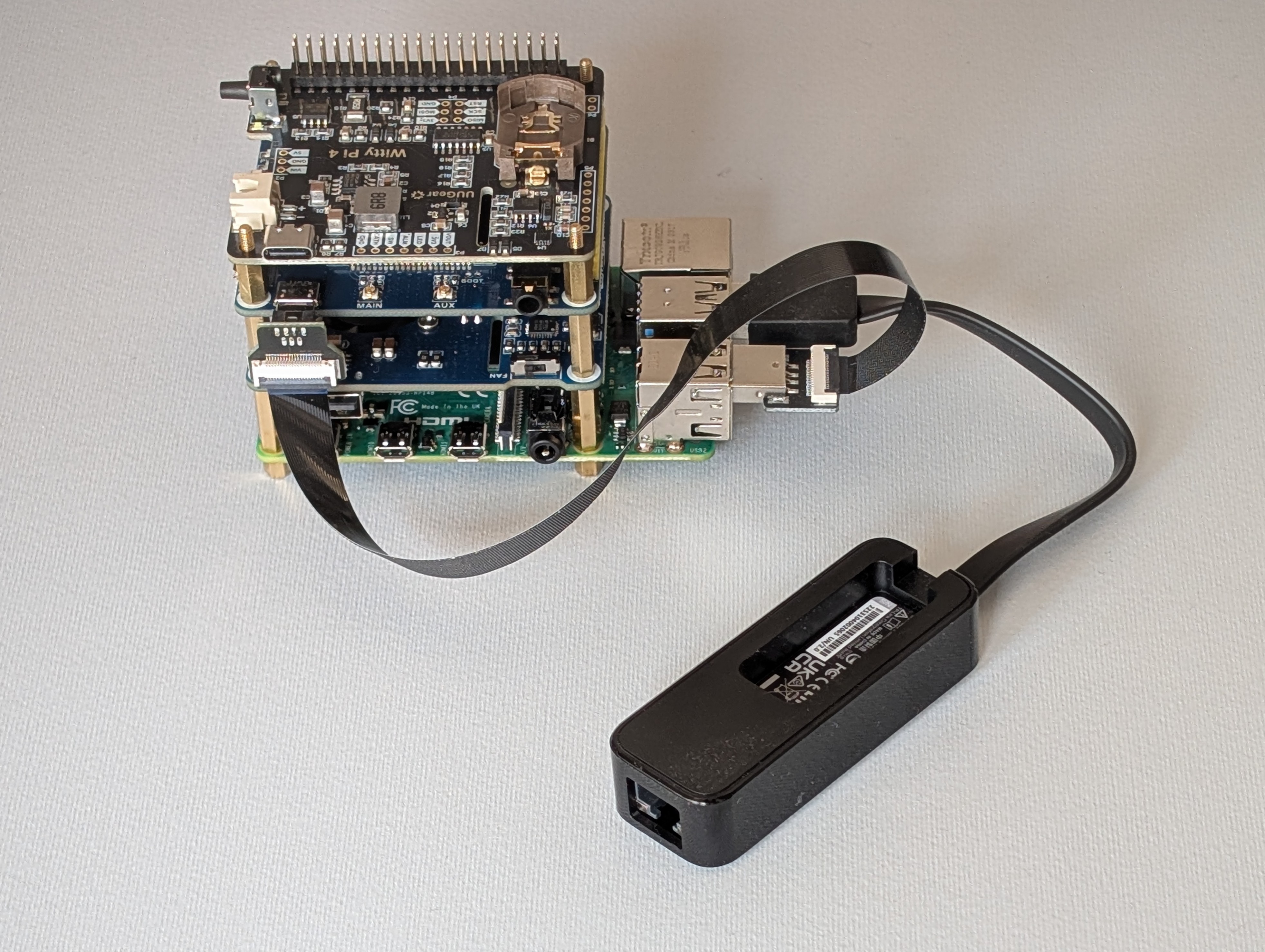 Complete hardware stack with USB-to-Ethernet adapter
The hardware is set; now it’s time to see how the software turns it into a cohesive, field-ready tool that stays reachable, resilient, and quiet in the background.
3. System Layout, Remote Management, and Resilience
This chapter covers the installed OS, the layout of implant files on the filesystem (scripts, logs, services, and timers), and operator access over WireGuard, including the peer configuration and a custom keepalive timer. It also introduces troubleshooting components, resilience settings, and an overview of the configured Discord bot for system diagnostic and management.
3.1 Implant system and structure overview
The base OS is Kali Linux for ARM. The implant’s file structure favors modularity, so each capability can evolve independently and maintenance stays simple. Files, services, timers, logs, and helper tools follow a structured layout, and a single configuration file controls behavior so individual scripts rarely need editing.
Design goals
- Each function is a script or a service that can be enabled, disabled, or swapped with minimal coupling.
- All runtime parameters live in
config.env, a single source of truth referenced by every script. - Long-running and recurring tasks are handled by systemd services and timers.
- Standalone helper tools are available system-wide for ad hoc actions.
- Every component writes to its own log directory, simplifying analysis and troubleshooting.
- The implant maintains a stable WireGuard VPN path for remote access, with lightweight keepalive and recovery mechanisms.
- Discord bot delivers quick status checks now, with easily extensible commands for a broader remote control in the future.
Filesystem layout
Everything related to the implant’s operation lives under /opt/implant, which keeps it in one place and organized as shown below.
1
2
3
4
5
6
7
8
/opt/implant
├── config.env
├── discord
├── logs
├── scripts
├── services
├── timers
└── wittypi
How to read this structure:
config.envholds all script parameters, such as interface names, WireGuard endpoint, Discord webhook URLs, network-capture settings, and more. Scripts always source this file.scripts/contains the main implant logic. Each script has a single responsibility, for examplespoof-target.shfor identity mimicry on the target link,bridge-sync.shwhich manages bridge configuration, orwg-keepalive.shwhich monitors VPN connectivity and tries to re-establish it if needed.services/andtimers/contain the corresponding systemd unit files. Services run continuously or on demand, and timers trigger periodic jobs without cron. Each unit executes its matching script fromscripts/folder.logs/stores per-component logs. Log rotation (via logrotate) is configured for most components to preserve history without exhausting storage.discord/packages the bot application and its virtual environmentwittypi/contains the power-management tooling provided by UUGear for configuring the Witty Pi.
3.2 WireGuard Configuration and Keepalive Timer
An automatic VPN link at boot is critical. Without it, operators cannot reach or manage the implant remotely. This section briefly shows the WireGuard peer configuration used on the implant and a small systemd timer that periodically checks reachability to increase resilience.
WireGuard Peer Configuration
The implant acts as a WireGuard peer and connects to the team’s server over 4G/LTE. Below is a portion of the implant’s wg0.conf:
1
2
3
4
5
6
7
8
9
# /etc/wireguard/wg0.conf
[Interface]
[...]
PostUp = ip route add <WG_SERVER_PUBLIC_IP> dev <LTE_INTERFACE>
PreDown = ip route del <WG_SERVER_PUBLIC_IP>

[Peer]
[...]
PersistentKeepalive = 25
Only a few optional parameters are shown above; the rest are standard peer settings. These options are included to improve resilience.
PostUp/PreDownadd and remove a specific route to the WireGuard server’s public IP. This prevents accidental default routes from overriding the path to the server, which could cut VPN access and leave the implant unreachable.PersistentKeepalive = 25sends periodic keepalives to keep LTE NAT mappings open, which helps with inbound SSH after idle periods. Given the keepalive timer described below, this setting is somewhat redundant, but it remains as an extra safeguard.
Finally, the WireGuard service is configured to start automatically at boot.
1
sudo systemctl enable --now wg-quick@wg0.service
WireGuard Keepalive (Timer)
The WireGuard keepalive timer checks reachability of the WireGuard server and restores connectivity if the tunnel appears dead. The timer runs a oneshot service periodically; on each run it sends a small burst of ICMP pings to WG_SERVER_IP. If all attempts fail, it appends basic diagnostics to the log, waits a few seconds, and reboots, attempting to re-establish the tunnel automatically.
This timer can be configured by editing the following parameters in config.env:
1
2
3
4
5
6
# [...]
# --- WireGuard Keepalive ---
WG_PING_ATTEMPTS=10
WG_SERVER_IP="10.8.0.1"
WG_KEEPALIVE_LOG="/opt/implant/logs/wg-keepalive/wg-keepalive.log"
# [...]
Below is a portion of the log generated just before the implant reboots due to the WireGuard server being unreachable.
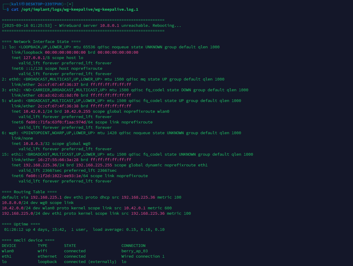 WireGuard keepalive log
With the peer configured, the service enabled at boot, and the keepalive timer monitoring and restoring the tunnel when needed, the WireGuard link stay resilient which is essential in this setup.
3.3 Troubleshooting services and timers
This section gives a brief overview of the systemd services and timers built specifically for troubleshooting. They originated from practical needs observed during development and testing, and they remain useful for installation, diagnostics, and recovery. The focus here is on Hidden Hotspot service and Power Monitor timer.
Hidden Hotspot (Service)
This service brings up an hidden Wi-Fi AP on wlan0 for emergency local access during implant installation, for example if the implant is not reachable from WireGuard VPN due to modem issues. It gives the operator a way to SSH in, run quick troubleshooting, and recover the box. After provisioning, the hotspot is rarely needed and can be left disabled.
The helper script lives in scripts/hidden-hotspot.sh and is exposed system-wide by adding a symlink:
1
sudo ln -s /opt/implant/scripts/hidden-hotspot.sh /usr/local/bin/hidden-hotspot
The script supports a small set of commands:
1
2
3
4
5
hidden-hotspot create  # create the NM profile from config.env (first-time set
hidden-hotspot update  # reapply changes from config.env (SSID/PSK/hidden/ifac
hidden-hotspot start   # bring AP up
hidden-hotspot stop    # bring AP down
hidden-hotspot delete  # remove the NM profile if no longer needed
The hotspot profile is created with NetworkManager (nmcli) using parameters from config.env:
1
2
3
4
5
6
7
8
# variables come from /opt/implant/config.env
# HOTSPOT_SSID, HOTSPOT_PSK, HOTSPOT_IFACE, HOTSPOT_HIDDEN

nmcli connection add type wifi ifname "$HOTSPOT_IFACE" con-name "$HOTSPOT_SSID" \
  ssid "$HOTSPOT_SSID" mode ap autoconnect no \
  802-11-wireless.hidden "$HOTSPOT_HIDDEN" \
  wifi-sec.key-mgmt wpa-psk wifi-sec.psk "$HOTSPOT_PSK" \
  ipv4.method shared
During staging, the operator can edits config.env and apply changes with hidden-hotspot update as specified.
1
2
3
4
5
6
7
8
9
10
11
12
13
#config.env

# [...]

# --- Hidden Hotspot ---
# To apply changes made to hotspot configuration, run:
# > hidden-hotspot update
HOTSPOT_SSID="berry_ap"
HOTSPOT_PSK="T3st1ng"
HOTSPOT_IFACE="wlan0"
HOTSPOT_HIDDEN="yes"

# [...]
Regarding the corresponding systemd service (/opt/implant/services/hidden-hotspot.service), the unit wraps the script for consistent launch and management. When enabled, it starts at boot after the network stack is up and brings the AP online. If startup fails, systemd retries according to the unit’s restart policy.
Power Monitor (Timer)
This timer periodically queries vcgencmd get_throttled, interprets, and logs indicators for undervoltage, frequency capping, and throttling. Below is an example of the power-monitor log.
 Power monitor log
This helps catch power-related issues and provides a broader view of what is happening on the implant’s power side, clarifying symptoms such as modem instability (leading to VPN interruptions) or failures to bring up interfaces like wlan0 (preventing the hotspot from starting). As noted, it proved useful during testing and is intended primarily for troubleshooting.
3.4 Resilience Hardening Measures
Let’s talk about some last additional resilience configuration used with primary goal of letting the implant always reachable under as much circumstances as possible.
Hardware Watchdog
To ensure the implant recovers from OS hangs or crashes and remains reachable, the Raspberry Pi’s hardware watchdog was enabled. It is a timer implemented in the Broadcom SoC that runs independently of the OS and can reset the board if software stops responding, even in the event of a kernel panic. In practice, a small userspace process “kicks” the watchdog at intervals; if the kick does not arrive in time, the watchdog forces a reboot.
On this build, the kernel driver bcm2835_wdt is loaded and the standard watchdog service is enabled so the timer is armed automatically at boot.
For validation during testing, a controlled panic was triggered via sysrq to confirm that the hardware watchdog reboots the system after the configured window. This proved the recovery path does not depend on userspace or a healthy kernel.
1
2
echo 1 | sudo tee /proc/sys/kernel/sysrq  # Enable sysrq commands
echo c | sudo tee /proc/sysrq-trigger     # Trigger a kernel panic
With this watchdog in place if the OS or kernel locks up, the board auto-resets and the WireGuard connection comes back, preserving remote access.
Preventing boot issues
During testing, occasional boot stalls were observed, which left the implant unreachable. Boot logs review pointed to delays while loading Bluetooth kernel modules and initializing the UART serial console. Since neither feature is required in this use case, both were disabled to improve boot consistency and unattended operation.
The Bluetooth drivers were the first source of delay or stalls. Blacklisting them prevented the kernel from loading the modules, and the related userspace units were disabled. After that change, those boot-stall events disappeared.
1
2
3
4
5
6
7
8
# /etc/modprobe.d/blacklist-bluetooth.conf
blacklist btbcm
blacklist hci_uart
blacklist bluetooth
blacklist rfcomm
blacklist btintel
blacklist btrtl
blacklist btusb
1
2
3
sudo systemctl disable hciuart.service
sudo systemctl disable bluetooth.service
sudo update-initramfs -u
The second culprit was the serial console on the Pi’s UART, which is typically used for debugging purposes. Leaving a console attached at early boot introduced again occasional stall. Removing the console parameters (e.g., console=serial0,115200) from the boot command line stopped the kernel from binding there during initialization.
1
2
# /boot/firmware/cmdline.txt (ensure no serial console parameters)
console=tty1 root=PARTUUID=<...> rootfstype=ext4 fsck.repair=yes rootwait net.i
After applying these changes, boot stalls have not been observed again, and the implant has remained reachable.
3.5 Discord Bot for Diagnostic and Remote Management
The Discord bot was developed to create a lightweight control and diagnostic interface for the implant, allowing operators to interact with it directly through Discord without requiring VPN access or SSH connectivity. Its main purpose is to automate simple diagnostic tasks, verify implant reachability, and in the future, serve as a base for remote automation and command orchestration.
At present, two commands are available:
| Command | Description |
|---|---|
/alive | Check if implant is reachable |
/status | Get detailed system status |
The explicit implant_ip argument was introduced early to support scenarios with multiple implants deployed across different targets, enabling operators to address them individually.
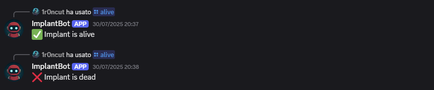 Example of /alive command output
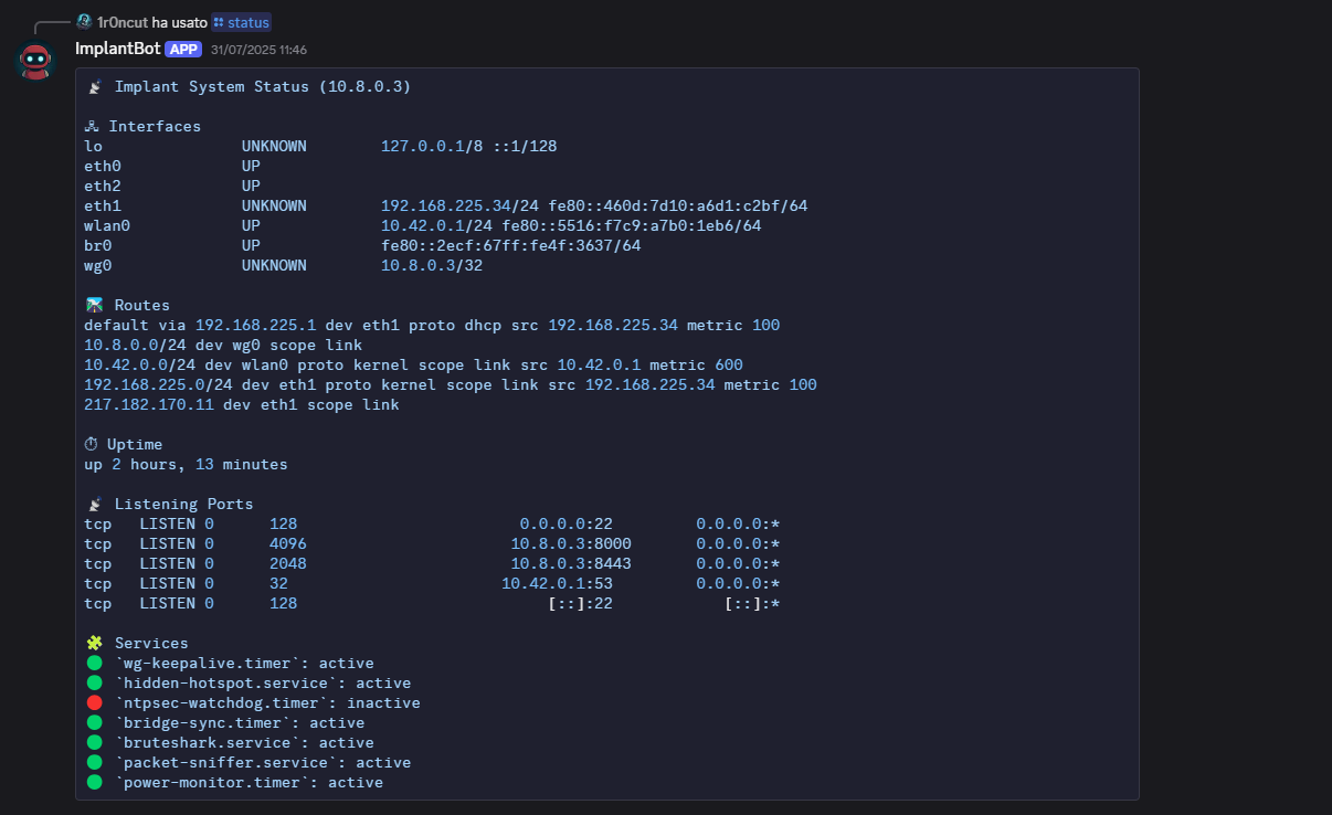 Example of /status command output
Architecture Overview
The system is composed of two Python services working together
Both components communicate through HTTP(S) protocol. The design was intentionally kept minimal, so that the entire control plane could be deployed with only two Python daemons managed by systemd.
VPS-Side Bot Implementation
The VPS-side bot logic is written within a Python script that uses the discord library. It runs as a background daemon, and awaits slash-command interactions from authenticated users.
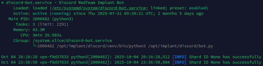 Discord bot service status
The following tree shows the modular on-disk layout of the VPS-side Discord bot, with commands isolated in their own modules.
1
2
3
4
5
6
7
8
9
10
11
/opt/implant/discord/
├── bot.py
├── commands
│   ├── __init__.py
│   ├── alive.py
│   ├── status.py
├── config.py
├── logs
│   └── bot.log
├── requirements.txt
└── venv
The bot.py script loads all commands dynamically on startup:
1
2
3
4
5
6
# Dynamically load commands
for filename in os.listdir("commands"):
    if filename.endswith(".py") and filename != "__init__.py":
        mod = __import__(f"commands.{filename[:-3]}", fromlist=["setup"])
        if hasattr(mod, "setup"):
            mod.setup(bot)
Each file under commands/ defines a standalone function that maps to a Discord command. When implementing a new server-side command, you only need to write its logic in a new dedicated file that follows a standard template. Below is the alive command implementation example.
1
2
3
4
5
6
7
8
9
10
11
12
13
14
def setup(bot):
    @bot.tree.command(name="alive", description="Check if implant is up", guild=...)
    @app_commands.describe(ip="Target implant IP address")
    async def alive(interaction: discord.Interaction, ip:str):
        await interaction.response.defer(thinking=True)
        try:
            async with aiohttp.ClientSession() as session:
                async with session.get(f"https://{ip}:8443/alive", ssl=False, timeout=10) as resp:
                    if resp.status == 200:
                        await interaction.followup.send(f"✅ Implant at {ip} is alive")
                    else:
                        await interaction.followup.send(f"❌ Implant at {ip} is dead")
        except Exception as e:
            await interaction.followup.send(f"❌ Implant at {ip} is dead")
Implant-Side API Server
Each implant hosts a small Flask web application exposed through Gunicorn. It listens on port 8443 and exposes one route per command, currently /alive and /status. As noted earlier, the VPS-side script uses these endpoints to interact with the implant.
Just like the VPS-side bot, the implant-side server application is also modular. The corresponding folders and files are structured as follows:
1
2
3
4
5
6
7
8
9
10
11
/opt/implant/discord
├── app
│   ├── commands
│   │   ├── alive.py
│   │   └── status.py
│   ├── __init__.py
├── certs
├── logs
├── requirements.txt
├── venv
└── wsgi.py
The systemd unit controlling the discord API server is stored at /opt/implant/services/discord.service:
1
2
3
4
5
6
7
8
9
10
[...]
[Service]
WorkingDirectory=/opt/implant/discord
EnvironmentFile=/opt/implant/config.env
ExecStart=/opt/implant/discord/venv/bin/gunicorn \
    --certfile=certs/cert.pem \
    --keyfile=certs/key.pem \
    --bind ${IMPLANT_WG_IP}:8443 \
    wsgi:app
[...]
As with the server-side bot.py, the __init__.py script dynamically imports each Python file in the commands/ directory:
1
2
3
4
5
6
7
# Dynamically register command routes
commands_path = os.path.join(os.path.dirname(__file__), "commands")
for fname in os.listdir(commands_path):
    if fname.endswith(".py") and fname != "__init__.py":
        mod = __import__(f"app.commands.{fname[:-3]}", fromlist=["setup"])
        if hasattr(mod, "setup"):
            mod.setup(app)
Below is the respective implant-side logic of the alive.py command shown before.
1
2
3
4
def setup(app):
    @app.route("/alive")
    def ping():
        return "", 200
At the moment, the API server listens only on the WireGuard interface and does not implement authentication; this will be added in a future version.
Implementing new commands
Given the modular approach, adding new commands is straightforward. To summarize, an operator has to follow these steps.
VPS-side:
- Create
commands/<name>.pycontaining asetup(bot)function. Insidesetup(bot), register the slash command with@bot.tree.command(…). This is required because the loader imports each module and calls itssetup(bot)entry point. - Implement the logic that calls the implant API server endpoint.
- Restart the bot service.
Implant-side:
- Create
commands/<name>.pycontaining asetup(app)that both registers the HTTP route for the command and implements the handler, returning a compact response (if not empty, JSON format is used for responses). - Restart the implant service (
discord.service) to load the new route.
Workflow Summary
Finally, let’s summarize the entire high-level workflow with an example. When an operator executes /status 10.8.0.3:
- The Discord bot interprets the command, extracts
implant_ip, and sends an HTTP GET tohttps://10.8.0.3:8443/status - The Gunicorn server on the implant routes the request to the corresponding module (
commands/status.py). - The module executes the diagnostic logic and returns a JSON response.
- The bot formats and sends the result back to the Discord channel.
Overall, this modular Discord bot, mirrored on both the VPS and implant sides, makes it simple to extend functionality and add automation and control features over time. In its current minimal form it is intended for quick diagnostics, and the same structure can be expanded later to support richer automation.
4. Summary and second part anticipations
This first part defined what the implant is, outlined the operational context that justifies its use, and distilled the core requirements guiding its design. The hardware overview focused on flexibility and field practicality: a side control channel over 4G for out-of-band access, Power over Ethernet to reduce reliance on mains power, and remote power control to handle worst-case scenarios, including battery-backed operation. The software section described the base OS and the /opt/implant layout, showing how systemd services and timers coordinate components. Resilience measures were highlighted, including the WireGuard connectivity channel, the hardware watchdog, and the removal of noisy configurations that could stall or expose the device. Separately, the implementation of a lightweight Discord bot was described, providing diagnostics and simple automation.
What will be included in Part 2?
- How the transparent bridge is created and managed in practice.
- Operation in the presence of NAC using 802.1X, keeping the legitimate asset authenticated while remaining inline.
- Device identity spoofing to work within the target network without introducing new and unknown assets.
- Camouflage in office environments, including the 3D case design, printing, and assembly leading to a first complete build.
After Part 2, this first implant build will be fully assembled, configurable, and ready for field use during red-team engagements.