PhantomPi: A Covert Red Team Implant (Part 2)

This article continues the technical overview of the red-team implant, moving from design goals and baseline configuration to how the device blends into corporate networks without adding endpoints. Part 2 centers on a core capability, bridge mode. The focus is on installing the device inline between corporate assets, remaining transparent even in 802.1X environments, and spoofing the inline device’s identity so operators can access the internal network as that device. The article closes with the final layer of concealment, a 3D-printed enclosure that camouflages the implant in plain sight.
This project was developed during my work at InTheCyber Group. Visit the InTheCyber Blog for more posts.
1. The Bridge Mode: A Deep Dive
One of the implant’s most important features is Bridge Mode: the ability to place the device inline between the corporate network and a target asset (for example a workstation, IP phone, or printer) while remaining transparent to that asset. In this configuration the implant forwards and bridges all traffic, mimics the device’s characteristics (IP, MAC, hostname, network configuration, etc.), and continuously sniffs and analyzes communications. Crucially, Bridge Mode also provides the remote red team operator with direct access to the internal network while appearing as the same identity as the inline device, avoiding the introduction of an additional endpoint. As noted in the introduction, the implant can alternatively obtain a new IP and act as a distinct device; this is functional but less stealthy.
This chapter explains how Bridge Mode is implemented on the implant, and walks through the configuration, services, and timers that make this behavior reliable, resilient, and covert.
1.1 Network Interfaces Roles and Configuration
At boot the implant exposes three Ethernet interfaces, each bound to a fixed role that must be preserved during installation and wiring:
- eth0 is the Raspberry Pi built-in NIC. It connects to the internal network and, when PoE is used, powers the device thanks to the Waveshare PoE module.
- eth1 is the LTE uplink provided by the USB modem. It is the path that keeps the implant reachable by remote operators.
- eth2 is cabled directly to the inline corporate asset, for example a workstation, IP phone or printer.
Predictable names tied to physical ports
With multiple USB NICs attached, enumeration order can change across reboots. Because each interface name carries a specific role that our scripts (shown later in this chapter) depend on, we need the kernel to assign the same name to the same device at every boot, for example, eth1 must always be the LTE modem and eth2 must always be the USB-to-Ethernet adapter. To guarantee this, each device was mapped to its designated physical USB port using udev rules that match the port’s base USB path (KERNELS) and then assign the intended name. The result is a deterministic, probe-order-proof mapping of roles to names, regardless of driver timing or device reseating.
To identify each port’s path, the following command was run against each interface name assigned at boot.
1
sudo udevadm info -a /sys/class/net/eth[X]
The output was examined to identify the KERNELS=="…" entry representing the base USB path.
 udevadm output showing the KERNELS value for USB path identification
The table below summarizes the logical roles and their physical USB port paths, establishing the fixed mapping between USB path, interface name, and device.
| USB path (KERNELS) | Device | Interface Name | Role |
|---|---|---|---|
| 1-1.3 | SIM7600G-H 4G modem (micro-USB → USB) | eth1 | LTE uplink / remote reachability |
| 2-1 | USB-to-Ethernet adapter | eth2 | Link to the inline corporate asset |
Because the mapping is bound to USB port paths, wiring must follow the assigned ports: the SIM7600G-H modem and the USB-to-Ethernet adapter must be connected to the Raspberry Pi ports shown in the figure, corresponding to USB paths 1–1.3 and 2–1 identified earlier.
 Physical USB port mapping for consistent interface naming
The highlighted KERNELS values are used in the udev rules to bind each physical port to its intended interface name. These rules are stored in /etc/udev/rules.d/10-persistent-net.rules with the following content:
1
2
SUBSYSTEM=="net", ACTION=="add", SUBSYSTEMS=="usb", DRIVERS=="?*", KERNELS=="1-1.3", NAME="eth1"
SUBSYSTEM=="net", ACTION=="add", SUBSYSTEMS=="usb", DRIVERS=="?*", KERNELS=="2-1", NAME="eth2"
After writing the file, udev was reloaded and the change made persistent so the kernel consistently binds names at boot.
1
2
sudo udevadm control --reload
sudo update-initramfs -u
Additionally, to prevent systemd’s predictable naming from superseding custom mappings, the Raspberry Pi boots with the kernel parameters net.ifnames=0 biosdevname=0 appended to the single-line /boot/firmware/cmdline.txt.
The actual udev configuration excludes the on-board Ethernet; as a non-USB integrated NIC it consistently enumerates as eth0, so its role remains stable without additional rules. Testing confirmed that, once the rules were applied, interface names remained consistent across reboots.
Preventing unintended network activity
To avoid unsolicited DHCP requests or automatic reconfiguration on the internal segment, the interfaces facing the enterprise network and the inline device are treated as unmanaged by the system network stack. Marking eth0 and eth2 as unmanaged keeps control with the implant services, which is essential for stealth.
Together, these choices produce a deterministic topology: the internal uplink is always eth0, the LTE backhaul is eth1, and the inline device link is eth2. Names remain stable, physical ports are fixed, and the system avoids unsolicited network actions, foundational for maintaining control and remaining stealthy.
1.2 Bridge Interface Configuration and Synchronization
Bridge Mode depends on a Linux software bridge that forwards frames transparently between the internal uplink and the inline device. With eth0 facing the corporate network and eth2 cabled to the asset, the implant aggregates them into a single bridge interface, br0, only when both sides are present and link is healthy. Automated control makes the implant follow the actual cabling, from setup to teardown of the bridge.
Bridge Sync (Timer)
Bridge management is orchestrated by a lightweight systemd-driven loop referred to as the Bridge Sync timer. At short, regular intervals it evaluates the state of eth0 and eth2, then converges the system into one of two outcomes:
- If both interfaces exist and have carrier, bring up br0 and enslave the two ports.
- If one side is missing or link is down, tear down br0 and clean residual state so the host returns to a safe, quiet posture.
At the core is a small bash program that performs three actions: (1) probe and normalize link state, (2) create or delete the bridge, and (3) log and signal state changes. In the snippet below, ethtool is used for link detection, with interfaces brought up beforehand.
1
2
3
if ethtool "$1" 2>/dev/null | grep -q "Link detected: yes"; then
    log "Interface $1 is UP and has carrier."
    return 0
When both sides are healthy, the script flushes any stray L3 configuration from eth0 and eth2, creates br0, and disables STP so the bridge neither sends nor reacts to BPDUs, preventing the implant from being announced and eliminating unnecessary control-plane noise. It then enslaves the member interfaces and brings the bridge up.
1
2
3
4
5
6
7
8
ip addr flush dev "$IFACE_COMPANY"
ip addr flush dev "$IFACE_TARGET"
ip link add "$BRIDGE" type bridge
ip link set "$BRIDGE" type bridge stp_state 0
ip link set "$IFACE_COMPANY" master "$BRIDGE"
ip link set "$IFACE_TARGET" master "$BRIDGE"
ip link set "$BRIDGE" up
echo 8 > "/sys/class/net/$BRIDGE/bridge/group_fwd_mask"
If prerequisites are not satisfied, the script tears down br0, cleans up auxiliary interfaces created by other components, removes related routes, and withdraws any temporary filtering rules.
Operational feedback is written to a dedicated log (/opt/implant/logs/bridgesync/bridge-sync.log), and, when enabled in /opt/implant/config.env, each bridge creation or deletion triggers a message to the implant’s control Discord server (the same used by the bot introduced in the previous chapter). This makes the physical state immediately observable, for example detecting when a laptop is connected or disconnected behind a docking station based on “bridge created” or “bridge removed” notifications.
 Discord notifications for bridge state changes
802.1X in the middle: making the bridge truly transparent
Now, let’s explain what was done to handle scenarios where the implant sits in the middle of an 802.1X deployment, commonly enforced by NAC systems. From the bridge-creation snippet above, the following command is critical.
1
echo 8 > "/sys/class/net/$BRIDGE/bridge/group_fwd_mask"
Linux bridges, by default, do not forward several link-local multicast destinations in the 01:80:C2:00:00:xx range because they are reserved for control protocols. 802.1X uses EAP over LAN (EAPOL) to the destination MAC 01:80:C2:00:00:03. Setting group_fwd_mask to 8 adjusts the mask so these frames are forwarded across the bridge instead of being consumed locally. In practice, this allows the full 802.1X exchange between the inline device (supplicant) and the switch (authenticator) to pass through. Without it, EAPOL-Start, Request/Identity, and subsequent keying messages do not reach the other side, and NAC authentication fails.
In theory, with this bridge configuration, 802.1X packets pass through, allowing NAC-enforced devices to operate normally even with the implant inline. To verify this behavior, a minimal lab was created to replicate the scenario. The actors and their 802.1X roles are listed below.
| Actor | 802.1X role | IP address | Notes |
|---|---|---|---|
| Inline device (Windows Laptop) | Supplicant (EAP Peer) | 192.168.1.19 | Receives/initiates EAPOL |
| Switch (NETGEAR GS108T) | Authenticator | 192.168.1.17 | Runs port-based 802.1X on the access interface |
| RADIUS server (VM) | Authentication Server | 192.168.1.18 | Validates credentials/identity |
| Implant (bridge) | N/A | N/A | Forwards EAPOL due to group_fwd_mask=8 |
The photo illustrates the setup summarized in the table.
 Lab setup for 802.1X testing with the implant inline
The configuration of each component in this setup is straightforward. On the Netgear switch, the RADIUS server used for 802.1X was added from the web GUI, as shown below.
 Netgear switch RADIUS server configuration
On port g2, 802.1X port authentication was enabled. Periodic Reauthentication is set to Enable, with a Reauthentication Period of 120 seconds, so the supplicant reauthenticates every two minutes.
 802.1X port authentication configuration on the Netgear switch
Next, a Linux VM bridged to the lab network runs FreeRADIUS. The EAP module is configured for certificate-based authentication (EAP-TLS) and references the server certificate, private key, and issuing CA, as shown in the module configuration. The switch’s management IP is defined in clients.conf with the shared secret, allowing the switch to contact the RADIUS server.
 FreeRADIUS EAP module and clients configuration
After configuration, FreeRADIUS is started with sudo freeradius -X. It then listens for authentication on UDP port 1812.
 FreeRADIUS running and listening for authentication requests
On the Windows laptop (supplicant), the issuing CA certificate is trusted, and a client-authentication certificate (including the private key) is installed in the certificate store. Windows is then configured to use that certificate for 802.1X authentication on the Ethernet interface.
 Windows certificate store (Trusted Root CA)
 Windows certificate store (Client Certificate)
With the configuration complete, the basic 802.1X setup works as expected. The Windows laptop (inline device) successfully authenticates and joins the internal network, which confirms that the implant bridge is transparently forwarding EAPOL traffic. As soon as the Ethernet cable is connected, FreeRADIUS logs show incoming authentication requests and the full EAP-TLS exchange, and a Wireshark capture displays the corresponding EAPOL/EAP frames on the wire.
 FreeRADIUS authentication logs and Wireshark EAPOL capture
 Wireshark EAPOL capture
This demonstration used a basic lab setup; broader testing in real environments is still required to assess robustness across diverse NAC configurations. In the next paragraphs, it will be shown how the implant spoofs the inline device identity, leverages the authenticated channel, and gains access to the internal network.
1.3 Intercepting and Analyzing Inline Device Network Traffic
Based on what has been described so far, the implant can now bring a bridge up or down when positioned between a company asset and the internal network. The goal is to leverage this man-in-the-middle position to not only relay traffic, but also capture the inline device’s traffic for analysis and potential extraction of sensitive or useful data. To this end, two systemd services are configured on the implant. This paragraph provides a brief overview of both.
BruteShark (Service)
BruteShark is an open-source network forensics and analysis tool that inspects live traffic or PCAPs to reconstruct sessions, map hosts, and extract credentials and password hashes. Typical outputs include cleartext usernames and passwords from protocols such as HTTP, FTP, Telnet, IMAP, and SMTP, as well as authentication hashes (for example, Kerberos, NTLM, CRAM-MD5, and HTTP-Digest) that can be exported in Hashcat-ready formats for offline cracking.
This project fits the use case of analyzing live inline-device traffic while the implant operates in bridge mode. BruteSharkCli is compiled and installed on the implant and wired to the bridge lifecycle. When the bridge-sync systemd timer creates the bridge (indicating that an inline device is active), it starts a systemd service named BruteShark, which runs a small Python wrapper that invokes BruteSharkCli to analyze traffic on eth2 (the interface connected to the inline device) and harvest credentials and hashes from the protocols mentioned above. The command executed by the wrapper is:
1
BruteSharkCli -p -l eth2 -m Credentials,NetworkMap,FileExtracting,DNS -o /opt/implant/logs/bruteshark
The Python wrapper parses the output in real time, deduplicates new “Credential” findings, logs them under the service’s log folder, and sends notifications to a private Discord channel (the same used by the bot described in Part 1, Chapter 3) via webhook, so operators see fresh credentials without polling the device.
 BruteShark credential notifications via Discord
Target Packet Sniffer (Service)
Because relying solely on BruteShark’s live parsing is undesirable, a companion service continuously captures raw traffic on eth2 with tcpdump, writing fixed-size PCAP chunks into a bounded ring to keep storage under control. It starts quietly on boot, requires no operator action, and ensures recent packets are always available for offline analysis.
1
2
3
4
5
6
# /opt/implant/scripts/packet-sniffer.sh
# [...]
tcpdump -i "$SNIFFER_INTERFACE" \
    -w "${SNIFFER_LOG_DIR}/${SNIFFER_FILE_PREFIX}.pcap" \
    -C "$SNIFFER_MAX_FILE_SIZE_MB" -W "$SNIFFER_MAX_TOTAL_FILES" -n -U
# [...]
As with the other services, all parameters are sourced from config.env, so operators can easily control how much traffic is retained (file size and ring depth).
1
2
3
4
5
6
7
8
9
# /opt/implant/config.env
# [...]
# --- Packet Sniffer ---
SNIFFER_LOG_DIR="/opt/implant/logs/packet-sniffer"
SNIFFER_INTERFACE="eth2"
SNIFFER_FILE_PREFIX="capture"
SNIFFER_MAX_FILE_SIZE_MB=200
SNIFFER_MAX_TOTAL_FILES=5
# [...]
With these two simple services in place, the implant better leverages its privileged man-in-the-middle position.
1.4 Mimicking the Inline Device Identity
An essential capability of the implant is to analyze traffic on the interface connected to the inline device (eth2) and spoof the device’s identity (IP address, MAC address, and hostname). The goal is to establish a controlled channel that allows an operator to access the internal network while impersonating the inline device, with the real device continuing to function normally. This avoids introducing new visible assets and preserves stealth. This paragraph provides a technical overview of the standalone spoof-target.sh script that implements this functionality.
Spoof-Target Script
The spoof-target.sh script enables stealthy impersonation of the inline device. It passively collects identity and network hints from eth2, then creates a veth pair in which veth0 is added to br0 and veth1 is assigned the target’s identity (IP and MAC address). This simplifies subsequent network operations by providing a dedicated interface on the implant for routing, with all traffic on veth1 presenting the inline host’s identity. In addition, isolation rules applied with ebtables, arptables, and iptables maintain stealth and ensure the real host continues to function normally while the spoofed interface provides a controlled channel for operator access.
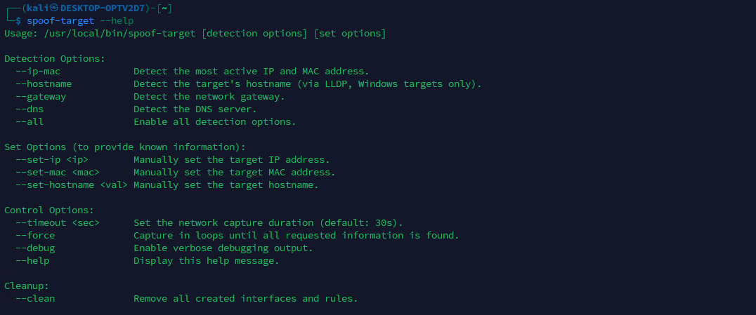 spoof-target.sh script help menu showing available options
Data collection phase: what gets detected and how
The script can take inputs manually or discover them automatically by listening on eth2 for a short window. The data of interest are: the inline host’s IP and MAC (mandatory for identity), hostname (optional but valuable for stealth), and the network’s default gateway and DNS server (useful for reachability and name resolution). In automatic mode (--all or granular flags), --timeout <sec> controls capture duration and --force repeats capture until all requested items are found.
Below is a brief overview of the strategies to automatically capture user requested data.
IP and MAC detection
Strategy: analyze ARP replies and pick the most frequent IP/MAC pair observed on eth2. This reliably identifies the directly attached host.
1
2
# Parse ARP replies for MAC and IPv4 of the sender
tshark -r "$CAPTURE_FILE" -Y "arp.opcode == 2" -T fields -e eth.src -e arp.src.proto_ipv4
This prefers stability over the first seen packet and reduces false positives.
Hostname detection
Strategy: trigger and parse LLDP. During development, it was observed that Windows endpoints with LLDP enabled disclose the hostname in LLDP responses.
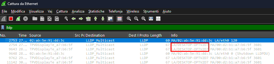 Wireshark capture showing LLDP hostname disclosure
A small helper, trigger-lldp.py, sends a minimal LLDP advertisement using Scapy library, replicating packets observed during testing to elicit a response. It then extracts the System Name from the capture, which provides the hostname to spoof.
1
2
3
4
# Start the LLDP trigger in background, then capture
sudo python3 /opt/implant/scripts/trigger-lldp.py &
# Extract hostname from the LLDP response of the target MAC
tshark -r "$CAPTURE_FILE" -Y "lldp and eth.src == ${SPOOFED_MAC}" -V | grep -E "System Name"
Note: this is the only active detection step; all others are passive. In testing, it consistently works only with Windows hosts that speak LLDP. Support for automatic hostname extraction on Linux distributions will be added in a future revision.
Gateway detection
Strategy: multi-step ARP heuristic. First choose the most “central” ARP participant, accept it if it looks like a typical gateway (x.x.x.1 or x.x.x.254). Otherwise, fall back to the most frequently requested ARP target.
1
2
3
4
# Conversational view
tshark -r "$CAPTURE_FILE" -Y "arp" -T fields -e arp.src.proto_ipv4 -e arp.dst.proto_ipv4
# Fallback: top ARP request destination
tshark -r "$CAPTURE_FILE" -Y "arp.opcode == 1" -T fields -e arp.dst.proto_ipv4
This approach is based on the assumption that all devices in the network typically issue ARP requests to discover the gateway’s MAC address, making the gateway one of the most frequently requested IPs.
Note: Another valid heuristic (partially implemented but currently unused) would involve selecting the IP that initiated ARP queries for the widest diversity of target IPs, which can also indicate a routing role.
DNS server detection
Strategy: look for unicast DNS queries to UDP 53 and pick the most common destination, excluding mDNS and LLMNR.
1
2
3
tshark -r "$CAPTURE_FILE" \
    -Y "udp.dstport == 53 and not ip.dst == 224.0.0.251 and not ip.dst == 224.0.0.252" \
    -T fields -e ip.dst | sort | uniq -c | sort -nr | head -n1
What has been described so far summarizes the required data and how it can be obtained automatically or supplied manually. Below is an example of an automatic detection run in which all requested items were identified.
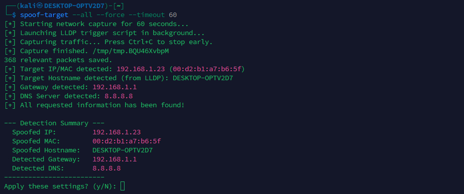 spoof-target.sh automatic detection results
As shown, the script always presents a recap and asks for confirmation before proceeding, since automatically detected values can occasionally be wrong and are sometimes easy for an operator to spot.
Note: Even if N is selected and the process does not continue, all detected values are written to a log file stored in
/opt/implant/logs/spoof-target/spoof-target.log, so nothing is lost.
Applying the spoofed identity
From the state shown above, once identity and network hints are in hand, the script constructs a safe impersonation path that does not disrupt the real host.
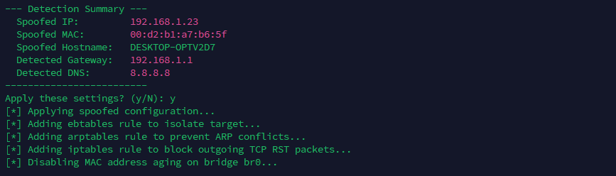 spoof-target.sh applying the spoofed configuration
In particular step by step operations performed are the following.
1. Create and attach the veth pair
A veth pair is two virtual Ethernet interfaces connected together, like a short patch cable: anything sent into one side comes out of the other.
In this setup:
- veth0 is plugged into the bridge br0. It acts as the bridge-facing Layer-2 end, carrying frames into br0 without its own IP/MAC configuration. This avoids putting an IP on the bridge itself or on a bridged port and keeps the bridge behavior simple and quiet.
- veth1 is given the spoofed identity (IP and MAC). Tools and routes bind to veth1, and its traffic exits via veth0 into the bridge, so on the wire it looks exactly like it came from the inline device. This also allows clean policy control and a predictable teardown by deleting the pair.
1
2
3
ip link add veth0 type veth peer name veth1
ip link set veth0 up
brctl addif br0 veth0
By analogy, this configuration creates an additional virtual identity plugged into the implant’s bridge through a virtual Ethernet patch cable: veth1 (the identity) connects to br0 via veth0, just as the inline device connects to br0 through eth2.
2. Assign spoofed IP, MAC and bring veth1 up
1
2
3
ip link set dev veth1 address <spoofed-mac>
ip addr add <spoofed-ip>/24 dev veth1
ip link set veth1 up
This gives the implant a twin of the inline host on a dedicated interface (veth1).
The mask is set to /24 as a pragmatic default for access VLANs common in labs and many enterprises. Future revisions will auto-derive the prefix (or allow operator override) when a different subnet is required.
3. Keep the real host safe from backflow
Drop any frames that could leak from the injected side back to the real machine on eth2.
1
ebtables -A FORWARD -i veth0 -o eth2 -j DROP
This avoids sending useless frames to the real endpoint.
4. Prevent ARP and TCP interference
Block ARP replies that the implant kernel might emit through the bridge.
1
arptables -A OUTPUT -o br0 --opcode Reply -j DROP
Block kernel-generated TCP RSTs on the spoofed interface to avoid tearing down the real host’s sessions. If this traffic is not blocked, the inline host may experience connectivity issues due to unexpectedly interrupted TCP sessions.
1
iptables -A OUTPUT -o veth1 -p tcp --tcp-flags RST RST -j DROP
These two rules preserve the inline host’s connectivity and keep the spoof quiet.
5. Disable MAC aging on the bridge
Ensure frames keep flooding so both the real endpoint and the spoof receive what they need.
1
brctl setageing br0 0
This makes the bridge behave like a hub from a learning perspective, which reduces misdelivery.
6. Align the hostname
Set the hostname and update /etc/hosts to match the inline asset when available.
1
2
hostnamectl set-hostname <spoofed-hostname>
# also ensure 127.0.1.1 maps to the spoofed hostname
For cleanup, the --clean option removes all spoofing-related configuration and restores the initial state. The bridge-sync systemd timer also performs this automatically when the bridge is destroyed.
Once configuration is applied, the network state appears as below. From this state, the implant can reach the internal network via veth1 using the spoofed identity, whether 802.1X is present or not.
 Network interfaces status
 Routes showing the spoofed veth1 interface
As noted throughout, several elements can still be refined in future versions. However, with network interface roles defined, the bridge implemented, 802.1X handled, and automation plus spoofing in place to impersonate the inline device before accessing the internal network, the software configuration and implementation overview is, for now, complete. The final requirement for stealth is physical: the implant must be camouflaged.
2. From tower to appliance. Building a case
As shown in Part 1, Chapter 2, at this point the stack resembles a small tower with cables everywhere. It draws attention, therefore it should be hidden inside something less suspicious.
 The implant hardware stack before enclosure
To address this, a basic 3D printer was used to produce a compact case that holds the full stack and routes the required pass-through connectors.
2.1 Printing an HAT for the USB-to-Ethernet Adapter
Before moving to the full enclosure, a better way to integrate the USB-to-Ethernet adapter into the tower was required. A slim, HAT-style tray was designed that the adapter slides into, with guide rails that hold it in place. The tray bolts onto the stack, so the adapter is mechanically secured. Once mounted, the module sits flush with the rest of the hardware, which makes internal cable routing cleaner and leaves enough clearance for the case.
 Fusion360 3D model of the USB-to-Ethernet adapter HAT
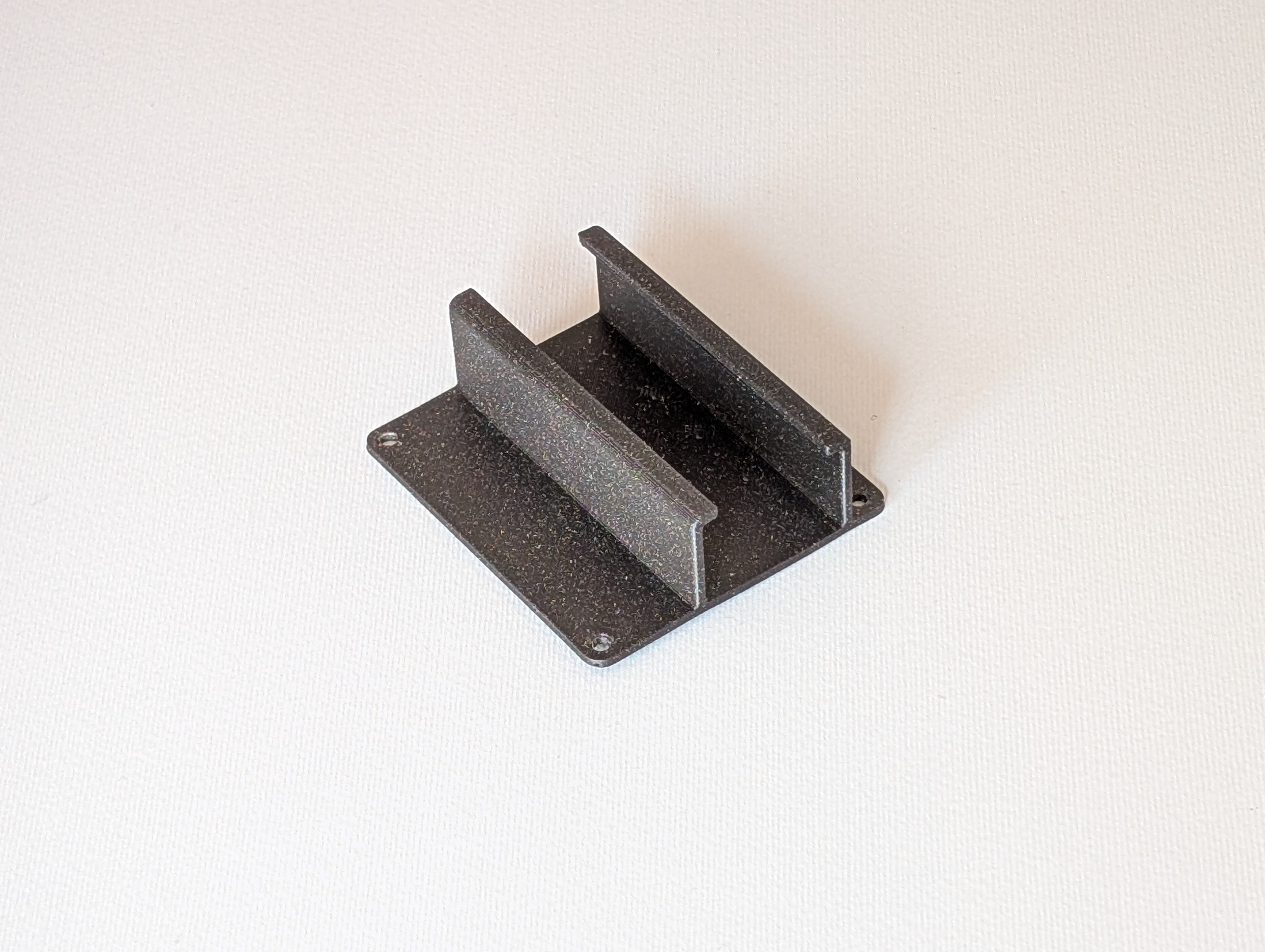 3D printed HAT for the USB-to-Ethernet adapter
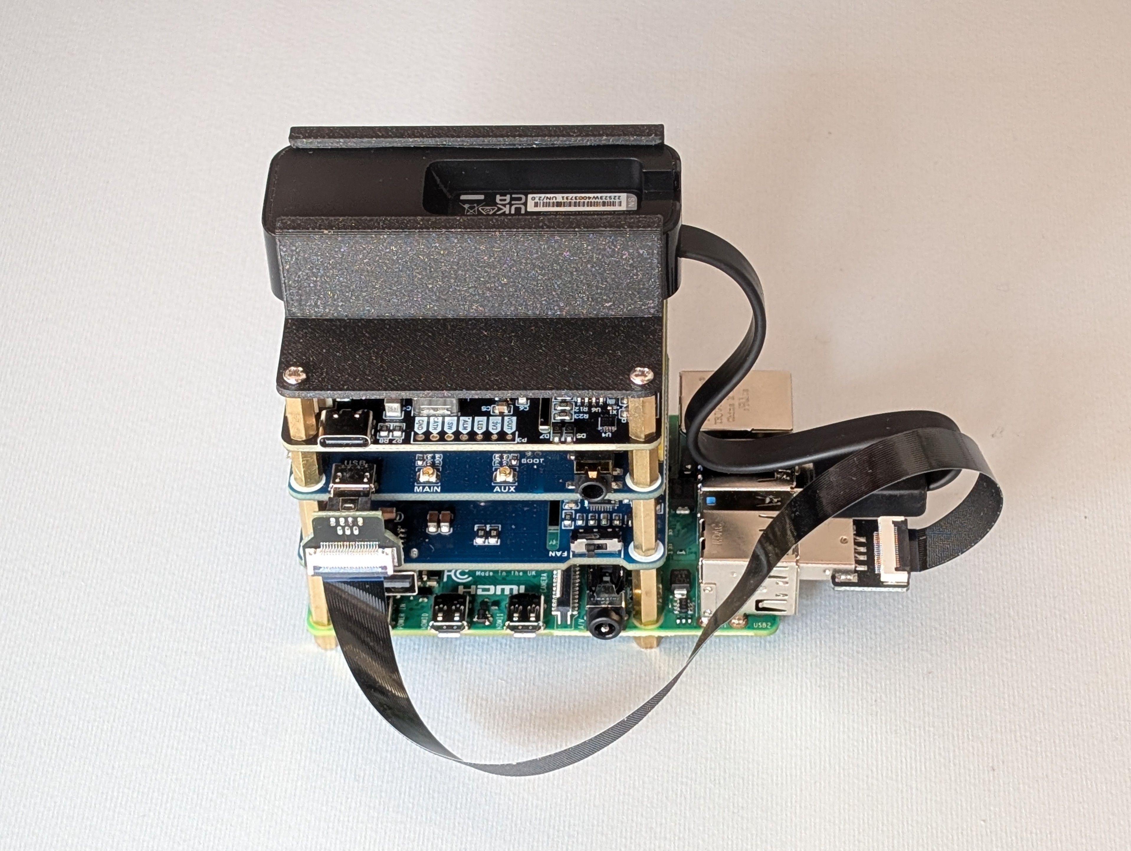 Final mounted stack
2.2 Case requirements
The enclosure must remain small while exposing exactly what is needed for bridge mode and power, and it must not trap heat. The design therefore includes:
- Two Ethernet pass-throughs, one for the corporate switch side and one for the inline device side.
- One USB-C power pass-through.
- Two SMA bulkheads for the LTE antennas.
- Ventilation openings to avoid thermal buildup.
- Rigid internal mounting with four screws to secure the stack.
- A top cover secured with four screws to conceal the internals.
2.3 3D model and print
The 3D model was created in Fusion360; the images below show the overall design and highlight how each requirement is implemented.
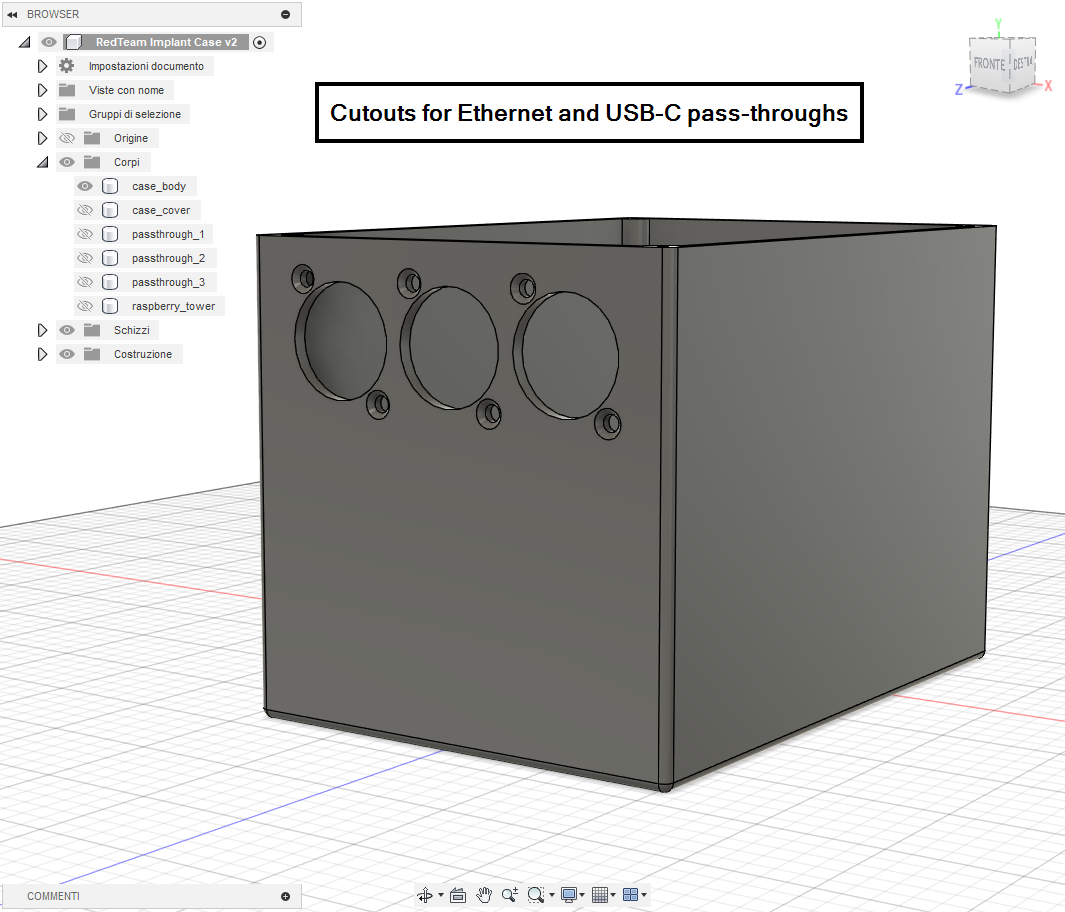 Fusion360 model showing Ethernet and USB-C pass-through cutouts
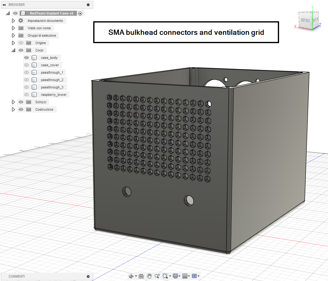 Fusion360 model showing SMA bulkhead connectors and ventilation grid
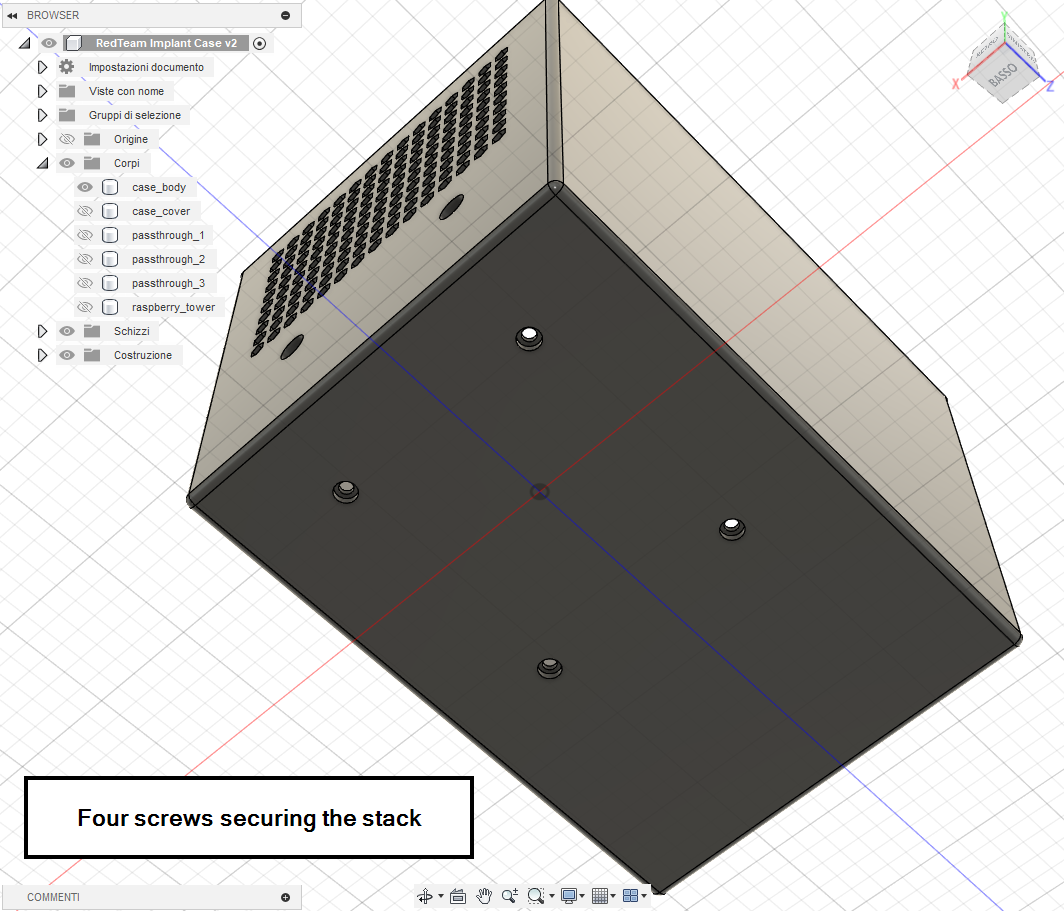 Fusion360 model showing four screws securing the stack
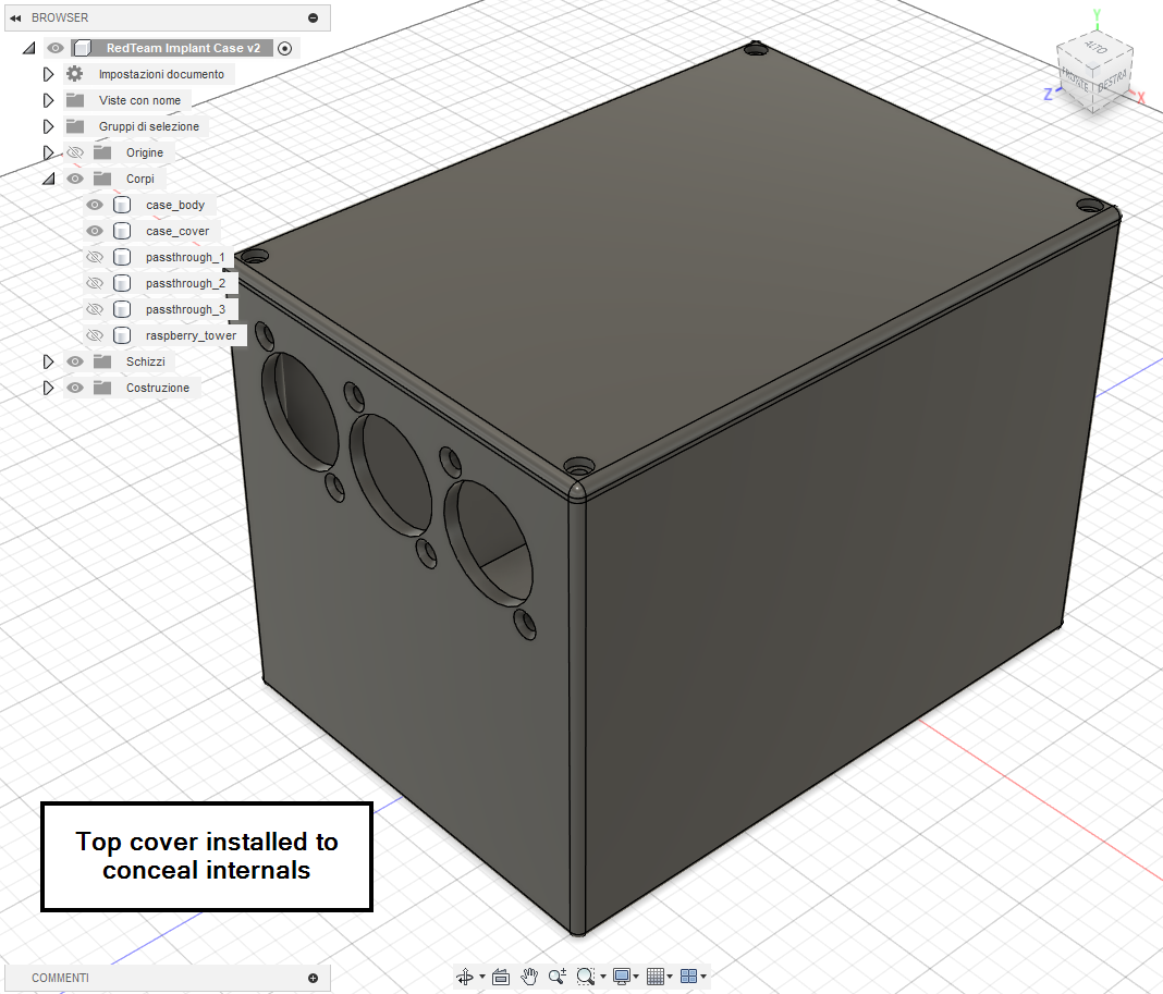 Fusion360 model with top cover installed
The case was modeled using the exact Pi 4 dimensions with clearances for each HAT. The goal was to keep the footprint as small as practical without restricting airflow or excessively cramping the cables. Final measures of the case are 140×100×100 mm (L×W×H)
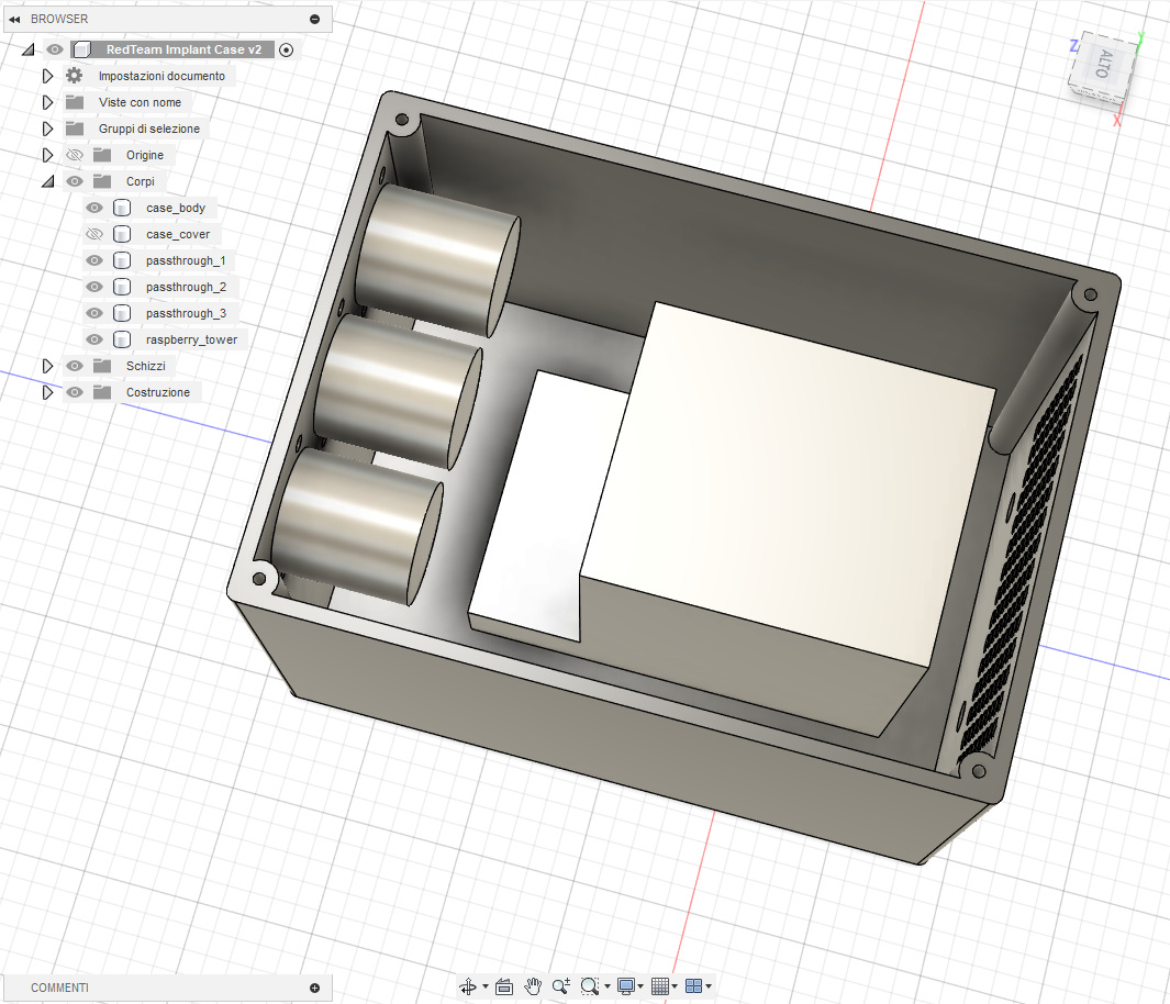 Fusion360 model internal view showing component placement
With the 3D model finalized, printing of the case proceeded.
 Bambu Lab printer producing the enclosure
2.4 Final assembly and carrying case
With the enclosure printed, the full stack was assembled inside the case and all connections were routed: two Ethernet leads, one USB-C power feed, and two RP-SMA pigtails for the antennas.
 Top view of assembled implant inside the case
 Completed PhantomPi with antennas attached (front)
 Completed PhantomPi with antennas attached (back)
To make the implant field-ready, it was paired with a compact carrying kit: two mountable antennas and a power supply with USB-C cable travel with the unit. After comparing dimensions, an almost perfect camera carry bag available on Amazon was selected that fits the implant and its accessories snugly. The bag also serves a secondary purpose, since in some scenarios it helps conceal the device when entering the target site.
 PhantomPi carrying kit: case, antennas, power supply, and carry bag
 PhantomPi packed in the camera carry bag
Here we are, the first implant version is finally complete. For how stealthy and invisible it tries to be within the target site and network, let’s call it PhantomPi!
3. Final considerations
The build described here already does the job and is ready to be deployed across different environments. Future iterations could explore LoRa as a backchannel for last-ditch troubleshooting, or other out-of-band paths that work from outside the building when cellular service is absent. They look unlikely, until you run into them on an actual job.
Additional software and hardware platforms are also viable directions. Commercially available OpenWrt-based routers with integrated cellular modems and multiple Ethernet interfaces provide a ready-made base. Since most of the work presented here is software, porting the logic to such platforms would be a practical avenue to explore.
A device like this earns its place both in full red team scenarios operated from outside the target and in assumed-breach exercises inside the network. The goal is a quiet and resilient red-team companion that deploys quickly, automates system and network configuration, and supports red-team operators, allowing them to focus on internal assessment and exploitation. Further improvements are planned, but that ongoing iteration is part of the fun!